Test of high voltage cable 10 kV Thread. Test cable lines
At the end of construction and mounting work Conduct cable lines receiving tests. At the same time, the intake was inspected, the insulation resistance is measured, they are tested with an increased DC voltage and check the lines phasing.
When testing power cables The megaommeter of 2500 V is revealed by coarse disorders of the isolation - grounding of the phases, a sharp asymmetry in the insulation of individual phases, etc. For the power cables to 1000, the insulation resistance should be at least 0.5 MΩ, for cables above 1000 V, it is not normalized.
Power cables above 1000 V are tested by increased voltage of the straightened current to detect local focused defects that may not be detected by a megoometer.
In accordance with PUE, power cables after the gasket are tested by a constant current of the straightened voltage of 6Un (for cables from 1 to 10 kV) and 5 UD (for cables 20 and 35 kV). The duration of the test of each phase is 10 minutes. The cable is considered to be withstrone the test if there was no breakdown occurred, there were no sliding discharges and currents of the current or its increasing after it reached the steady value. When testing, the voltage smoothly (1-2 kV / s) is raised to the norms provided by norms and support unchanged during the entire period. The countdown starts from the moment of the application of the total test voltage. At the last minute, the tests of each cable phase are counted according to the readings of the microammeter of the leakage current. The ratio of the larger current to the smaller (asymmetry coefficient) is determined. For cables with good insulation, this ratio is less than two, for cables with satisfactory insulation, leakage currents are within the following limits: up to 300-500 (for 6-10 kV cable lines) and up to 700 μA (for lines 20 35 kV). After testing with increased voltage, the cable is again measured by a megaomemeter, perform a phasing and include a line under the operating voltage.
If the current shocks were noted when the cable line was tested, the test stops and find the place of damage.
To find the place of damage in cables, it is required to reduce the transition resistance in this place, for which the cables burn. Special installations for burning cables industry does not produce, so they are not considered in this manual. After the end of the proceeding process, the resistance at the site of the breakdown decreases to several dozen ohm.
To find faces damage to power cables, the following methods are used: relative (with which they determine the distance from the measurement location to the place of damage) and absolute (with which the damage is quite accurately indicate the place of damage directly on the cable line route). In the applied practice, both methods are usually used, while the relative method allows you to quickly (but not exactly) assess the distance to which the operator should go, and using the absolute method, clarify the place for excavations from relative methods is the most common pulse, from absolute - induction.
The pulse method is based on measuring the pulse passing time from one end of the line to the place of damage and back. To find the place of damage in the cable line, the pulse method uses a special device. When the device is turned on, the probe pulses are sent to the line, which, spreading through it, is partially reflected from the inhomogeneities of the wave resistance and return to the place where they were sent from. With a known pulse propagation rate V (the average speed of propagation for most cables 3-35 kV with paper-oil insulation (160 ± 1) m / μs, it does not depend on their cross section and length) and the distance to the place of damage 1x can determine the time of the pulse of the TR -2IX / V, therefore, LX \u003d VTX / 2.
The basis of the validity of the instruments is the principle of sensing the system under study by the voltage pulse with the indication of the processes occurring on the screen of the electron beam tube (CRT). When measuring, the reflected pulse from the place of damage is found on the screen and determine the time shift between the moment.
Adjusting secondary chains
After checking the installation of panels, remote controls and individual devices of protection, automation and control of external ties, measured insulation resistance cables, wires, clamps, electromagnet coils and contactors, as well as relays in a fully assembled scheme relative to the "land" (cable shell, housing, panels, Cabinet or shield). The insulation resistance between different circuits is also tested, electrically not related, for example, between circuits of control and alarm circuits. It must be at least 0.5 MΩ. The substations separately measure the insulation resistance of highways and control bins, alarms, voltages and power electromagnets. It must be at least 10 MΩ for all DC and AC shoins (with disconnected secondary circuits) and at least 1 MΩ for each portion of attaching secondary circuits and circuits of switches.
The secondary chains, the resistance of the insulation of which satisfy the standards, are tested by an increased voltage of 1000 V AC from a special installation for 1 min. In the absence of installation, it is allowed to test the megaommeter 2500 B and for 1 min. The test voltage is applied to secondary circuits of protection schemes, signaling and measurement controls with all attached devices (switches, fuses, starters, contactors, relays).
Before testing follows:
Thoroughly inspect all the equipment, panels, cables and clamps to which increased voltage will be supplied, and take the necessary safety measures;
Disable all grounds that are available in the schemes, and the devices, the test voltage of which is below 1000 V;
Shunt condensers and coils with high inductance (winding of current transformers, electromagnets and coils of some relays and contactors) to avoid the appearance of voltage resonance and overvoltage related;
Spread the chains of semiconductor devices and winding the stress of instruments, meters, voltage relays and all high-resistance in the schemes;
Disconnect all sources of direct and alternating current.
To reduce the number of tests with high voltage, it is recommended to combine the tested chains into one on the fuses, automata, keys and clips. After the test, the insulation resistance is measured (it should not decrease)
After checking schemes and insulation tests, adjustrate individual relays (current, voltage, time, frequency, thermal, etc.) and devices. Check the interaction of the relay and switching equipment, for which the operational current is supplied to the circuit, pre-determining the polarity or phasing of the supplied voltage. Next, check the interaction of the relay and equipment by turning on the corresponding circuits using control devices or closing and opening manually to the relay contacts in a specific sequence.
The interaction of relays and equipment in control, protection, alarm and automation schemes are monitored at rated voltage and at 80% UAV. Contactless schemes are checked at a voltage of 85% UAn, UD and 110% UAN. At the same time, the work of all equipment must be a clear.
© All materials are protected by the Law of the Russian Federation on the copyright and Civil Code of the Russian Federation. It is prohibited to complete copying without the permission of the resource administration. Partial copying with a direct reference to the original source is allowed. Author of the article: Collective of engineers of JSC Energetics
Any qualitatively manufactured conductor designed for increased voltage during installation work may have technological damage. To avoid emergency situations during commissioning, when an increased load is raised, you must make sure the integrity of the cable line. During operation, the inevitable processes of destruction of the material from which the conductor is made, so it loses its isolation characteristics. To ensure safe operation, it is necessary to conduct periodic cable tests with increased voltage. Next, we will tell you exactly what the test work is carried out.
Typical damage to cables
According to statistical data, the most frequent damage is the cause of failure electrical cables are:
- Damage to the integrity of the protective shell as a result of incorrect technological work.
- The destruction of isolation due to the aging of the material from which the cable is made due to the violation of the test technology.
- The appearance of cracks and gaps in the protective screen, which violate the insulation functions.
Test species
In accordance with the established standards and rules for testing electrical equipment, it is necessary to make sure that the claimed challenges of the cable presented. If any inconsistencies are revealed, allowing and the more exploited such lines is categorically prohibited.
Test types:
- The insulation disorder is checked by determining the value of its resistance using the instrument, which is called the megommeter, the voltage supply is 2,5kV. If the insulation resistance is higher than 500 com, it is considered that it is enough for cable lines to 1000 V. If the voltage is more than 1000 V, there is no rationing, but according to PTEEP (clause 6.1. And Table 37) and PUE (p. 1.8.37 and Table 1.8.34), the value should not be below 10 MΩ. In more detail about, you can learn from our article.
- It is possible to identify the presence of damage by conducting high voltage tests. In this method, they are observed, namely their asymmetry in phases and character. This method is more efficient, because it allows you to identify insulation damage, which were not detected using a megommeter. Increased load produces breakdown in problem places. To carry out such a test on one of the cable veins, the voltage is supplied, and the remaining veins and the shell ground.
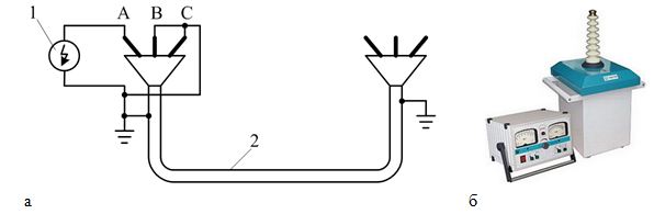
Figure above shows: a - electrical scheme for insulation check; B - Showing a high-voltage installation for testing work. In the scheme:
- 1 is an enhanced load generator;
- 2 - conducted by the integrity of the conductor.
A different type of insulation requires a certain time to establish a breakdown. For example, the cable line tests on the increased voltage of 2000-35000 in is required 5 or 10 minutes of the time of the permanent load for each vein. If the tests are designed for the cable line designed for 110000-500000 V, the voltage is fed to the cable within 15 minutes. During the test, the current asymmetry distributed by phases should not exceed 50%.
In case of operation of the cable in parallel with the other, be sure to perform its phasing. This is achieved by the method of feeding the operating voltage to one of the ends of the cable and at the other end is measured voltage.

- High voltage linehaving an oil-filled withdrawal, which is commonly used in highways, where 110-500 kV load is transmitted, the test of its oil or other fluid is tested for compliance with the declared characteristics.
- The high voltage line of the cable connection is checked for corrosion protection:
- When the cable has a metal shell, and the products are used for laying in the ground, its specific resistance does not exceed 20 Ohm / m.
- When the conductor has a metal shell, and the products are used for laying in the ground, its specific resistance is less than 20 Ohm / m.
- When the shell armored and it must be checked for damage, as well as the destruction of protective covers.
- When the cable is designed in the high pressure zone of steel pipelines, and the soil has a different degree of aggressiveness. The high-voltage line of the cable connection is subjected to measurements of the values \u200b\u200bof potentials and currents wandering in the shell.
- The high voltage line is checked on the integrity of the conductive lives, as well as the phasing by an ommeter device. For which one core is determined and it is continued to be carried out, alternately, the measurements of the resistance of the closed chains of all lived. A deliberately intact conductor can be used as a reference core.
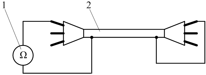
where: 1 - device Ommeter; 2 - Checked Product.
- The high-voltage line designed to operate on an increased voltage of 20,000 V and more, it is necessary to set the resistance value of each individual cable conducted.
- Check for current distribution on the veins. The value of non-uniformity on the veins should not exceed more than 10%.
- The high voltage line of the cable bond (from 110,000 V to 500000 V) having an oil-filled isolation is subjected to determining the content of non-soluble gases. For such highways, their value should not exceed 0.1%.
- The cable line, where an increased voltage of 20 kV and above is present, is subject to the determination of the value of the electric container. As a rule, in such cases, two techniques are used: using a voltampermeter using a method of determining using a pavement scheme.
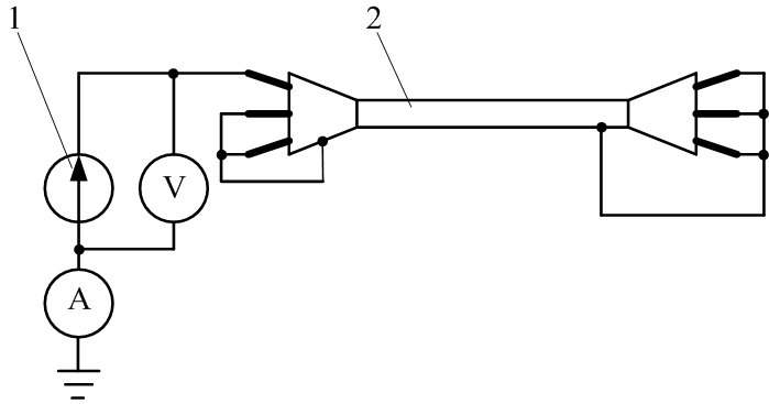
1 - load source; 2 - Checked Product.
- The high-voltage line (from 110,000 V to 500,000 V) having an oil-filled isolation, it is necessary to check for gases of not only insoluble, but also soluble. For this, a chromatographic method for determining such substances is used.
- The resistance of the grounding devices, couplings of end and cable seals, metal structures, of which are cable, as well as feeding points are also performed.
- The high voltage lines of the cable bond (110000 V), the shells of which are made of plastics, are tested for 1 min with an increased straightened voltage.
What else is important to know?
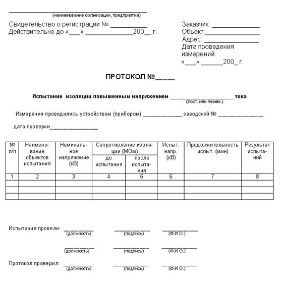
After testing work, the result is submitted to the protocol, such as on the sample:
As for the timing of testing, they are as follows:
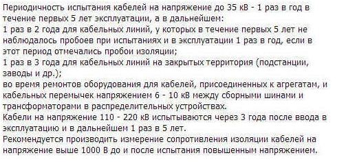
Well, it is important to say that for work, such devices such as IRC-5, AID-70 and AII-70 are most often used!
Power cable lines
Power cable lines voltage up to 1 kV are tested according to claims 1, 2, 7, 13, voltage above 1 kV and up to 35 kV - according to PP.1-3, 6, 7, 11, 13, with a voltage of 110 kV and higher - in The full amount provided for by this paragraph.
1. Checking the integrity and phasing cable lived. The integrity and coincidence of the phases of the plug-in cable veins are checked.
2. Measurement of insulation resistance. It is made by a 2,5 kV voltage megaommeter. For power cables up to 1 kV, insulation resistance should be at least 0.5 MΩ. For power cables above 1 kV, insulation resistance is not normalized. Measurement should be made before and after testing the cable with increased voltage.
3. Test with increased voltage of the straightened current.
Test voltage is accepted in accordance with Table. 1.8.39.
Table 1.8.39 Test voltage of rectified current for power cables
________________
* Tests with a straightened voltage of single-core cables with plastic insulation without armor (screens) laid in air are not produced.
For cables to voltage up to 35 kV with paper and plastic insulation, the duration of the application of the total test voltage is 10 minutes.
For cables with rubber insulation on a voltage of 3-10 kV, the duration of the application of the total test voltage is 5 minutes. Cables with rubber insulation on voltage up to 1 kV testing increased voltage are not subjected.
For cables for a voltage of 110-500 kV, the duration of the application of the total test voltage is 15 minutes.
Permissible leakage currents depending on the test voltage and the permissible values \u200b\u200bof the asymmetry coefficient when measuring the leakage current are shown in Table 1.8.40. The absolute value of the leakage current is not a brave indicator. Cable lines with satisfactory insulation must have stable leakage current values. When testing, the leakage current should decrease. If the leakage current value is reduced, as well as when it is increasing or increasing the current, the test is performed before detecting a defect, but not more than 15 minutes.
Table 1.8.40 Leakage currents and asymmetry coefficients for power cables
| Cables voltage, kV | Test voltage, square | Permissible values \u200b\u200bof leakage currents, ma | Permissible values \u200b\u200bof asymmetry coefficient () |
| 6 | 36 | 0.2 | 8 |
| 10 | 60 | 0.5 | 8 |
| 20 | 100 | 1.5 | 10 |
| 35 | 175 | 2.5 | 10 |
| 110 | 285 | Not normalized | Not normalized |
| 150 | 347 | Also | Also |
| 220 | 610 | " | " |
| 330 | 670 | " | " |
| 500 | 865 | " | " |
With a mixed laying of cables as a test voltage for the entire cable line, take the smallest of test voltages to Table. 1.8.39.
4. Test voltage of the variable current of 50 Hz.
Such a test is allowed for cable lines to a voltage of 110-500 kV instead of the test with straightened voltage.
The test is made with voltage (1.00-1.73). It is allowed to test by turning on the cable line to the rated voltage. Test duration - according to the manufacturer's instructions.
5. Determination of active resistance lived. It is performed for 20 kV lines and above. The active resistance of the cable line cable line, shown to 1 mm section, 1 m of length and temperature +20 ° C should be no more than 0.0179 ohms for copper veins and no more than 0.0294 ohms for aluminum veins. The measured resistance (powered by the specific value) may differ from the specified values \u200b\u200bof no more than 5%.
6. Determination of electrical working capacity lived.
It is performed for 20 kV lines and above. The measured capacitance should not differ from the results of factory tests by more than 5%.
7. Check protection against wandering currents.
The actions of the established cathode protection are performed.
8. Test for the presence of undisputed air (impregnating test).
It is produced for oil-filled cable lines 110-500 kV. The content of undisguised air in oil should be no more than 0.1%.
9. Testing feeding units and automatic heating of end couplings.
It is produced for oil-filled cable lines 110-500 kV.
10. Checking anti-corrosion protection.
When accepting lines and during operation, the operation of anti-corrosion protection for: is checked:
Cables with a metal shell laid in soils with an average and low corrosion activity (the resistivity of the soil is above 20 Ohm / m), with the average temperature density of the leakage current to the ground above 0.15 mA / dm;
Cables with a metal shell laid in soils with high corrosion activity (the resistivity of the soil less than 20 Ohm / m) with any average daily current density into the ground;
Cables with unprotected shell and destroyed armor and protective covers;
The steel pipeline of high pressure cables, regardless of the aggressiveness of the soil and the types of insulating coatings.
When checking, the potentials and currents in the cable shells and the electrical power supply parameters (current and voltage of the cathode station, drainage current) are measured in accordance with the guidelines for the electrochemical protection of underground energy facilities from corrosion.
Evaluation of the corrosion activity of soils and natural waters should be made in accordance with the requirements of GOST 9.602-89.
11. Determination of the characteristics of the oil and insulating fluid.
The definition is performed for all elements of oil-filled cable lines to a voltage of 110-500 kV and for terminal couplings (inputs in transformers and steering) cables with plastic insulation to a voltage of 110 kV.
Samples of oils of grades C-220, MN-3 and MN-4 and the insulating fluid of the PMS brand must satisfy the requirements of the norms of Table.1.8.41 and 1.8.42.
Table 1.8.41 Norms on the quality indicators of oils of grades C-220, MN-3 and MN-4 and insulating fluid of the PMS brand
Note. Tests of oils not specified in Table. 1.8.39, to be produced in accordance with the requirement of the manufacturer.
Table 1.8.42 Tangent Angle of dielectric loss of oil and insulating fluid (at 100%%, no more, for cables for voltage, kV)
| 110 | 150-220 | 330-500 |
| 0,5/0,8* | 0,5/0,8* | 0,5/- |
________________
* In the numerator, the value for oils of grades C-220, in the denominator - for MN-3, MN-4 and PMS
If the values \u200b\u200bof the electrical strength and degree of degassing MN-4 oil correspond to the standards, and the TG δ values \u200b\u200bmeasured according to the GOST 6581-75 method exceeded in Table.1.8.42, the oil sample is additionally kept at 100 ° C for 2 hours, Periodically measuring. When the value of Tg Δ, the oil sample is reduced at a temperature of 100 ° C until the steady value is obtained, which is accepted for the control value.
12. Measurement of grounding resistance.
It is produced on the lines of all stresses for end sealing, and on the lines of 110-500 kV, in addition, for metal structures of cable wells and feed points.